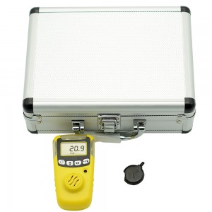
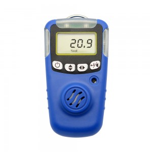
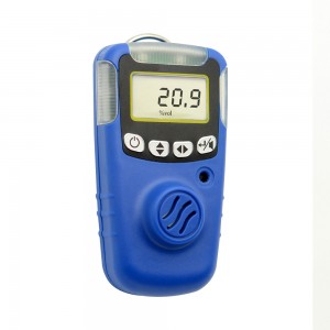
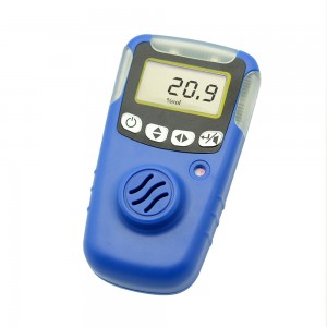
Single Gas Detector User’s
For security reasons, the device only by suitably qualified personnel operation and maintenance. Prior to the operation or maintenance, please read and fully manage all solutions to these instructions. Including operations, maintenance of equipment and process methods. And a very important safety precautions.
Read the following Cautions before using the detector.
Table 1 Cautions
| Cautions |
| 1. Warning: Unauthorized replacement of replacement parts in order to avoid the impact of the instrument Normal use. 2. Warning: Do not disassemble, heat or incinerate batteries. Otherwise battery possible explosion, fire or chemical burn hazard. 3. Warning: Do not calibrate the instrument in hazardous locations or set parameters. 4. Warning: all factory pre-calibrated instrument. Users use recommended calibration once at least six months in order to maintain a quasi-instrument Accuracy. 5. WARNING: Be sure to avoid using the instrument in corrosive atmospheres. 6. Warning: Do not use solvents, soaps, cleaning or polishing agents outside Shell. |
1. Product components and dimensions
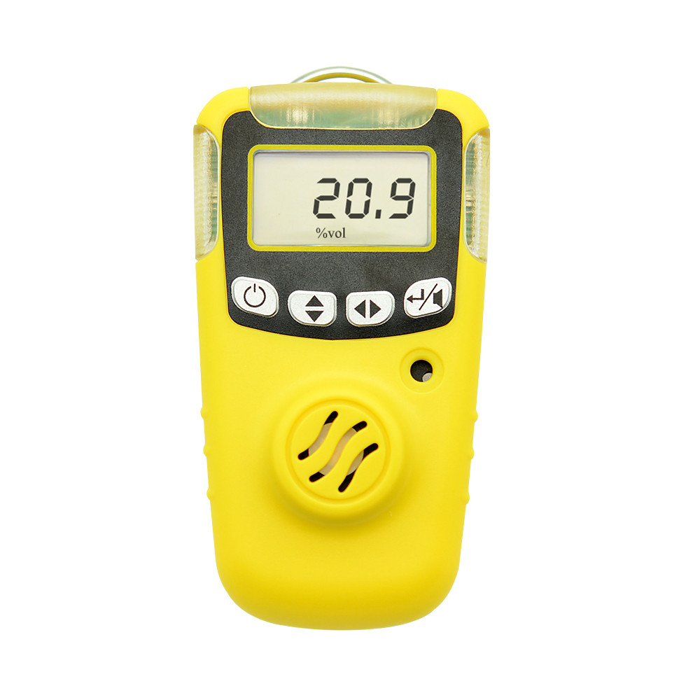
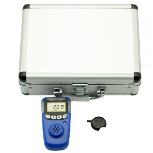
Product appearance shown in Figure 1:
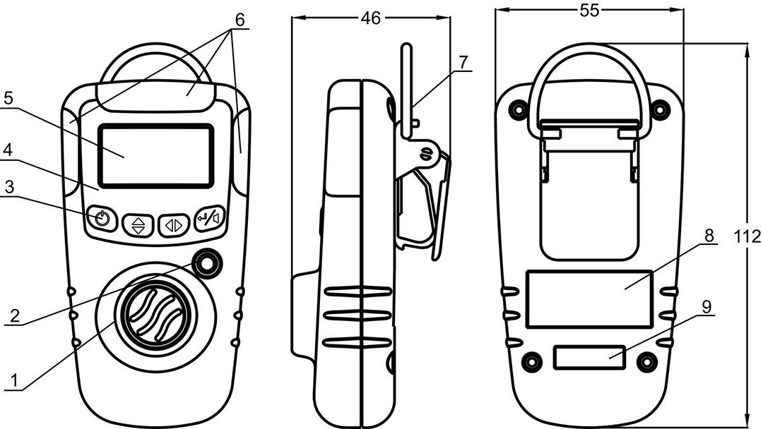
Figure 1
Appearance description as shown in Table 2
Table 2
|
Item |
Description |
|
1 |
Sensor |
|
2 |
Buzzer (audible alarm) |
|
3 |
Pushbuttons |
|
4 |
Mask |
|
5 |
Liquid crystal display(LCD) |
|
6 |
Visual alarms bars(LEDs) |
|
7 |
Alligator clip |
|
8 |
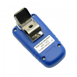
Nameplate |
|
9 |
Product ID |
2. Display Description
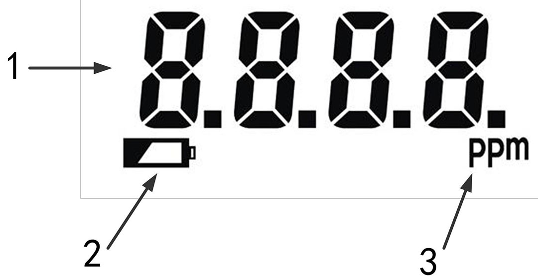
Figure 2 Display Elements
Table 3 Display Elements Description
| Item | Description |
| 1 | Numeric value |
| 2 | Battery(Display and flashes when the battery is low) |
| 3 | Parts per million (ppm) |
3. System parameters
Dimensions: Length * width * thickness: 112mm *55mm* 46mm Weight:100g
Sensor Type: Electrochemical
Response time: ≤40s
Alarm: Audible alarm≥90dB(10cm)
Red LED light alarm
Battery Type: CR2 CR15H270 lithium batteries
Temperature Range:-20℃ ~50℃
Humidity:0~95% (RH) Non-condensing
Common gas parameters:
Table 4 Common gas parameters
| Measured gas |
Gas Name |
Technical Specifications | ||
|
Measuring range |
Resolution |
Alarm | ||
|
CO |
Carbon monoxide |
0-1000ppm |
1ppm |
50ppm |
|
H2S |
Hydrogen sulfide |
0-100ppm |
1ppm |
10ppm |
|
NH3 |
Ammonia |
0-200ppm |
1ppm |
35ppm |
|
PH3 |
Phosphine |
0-1000ppm |
1ppm |
10ppm |
4. Key Description
Key functions as shown in Table 5
Table 5 Key Description
| Item | Function |
 |
Standby mode, the menu button |
| Long press for power on and off button | |
| Note: | |
| 1. To start gas detection alarm, press and hold the button for 5 seconds. After the gas detection alarm through a self-test, then begin normal operation. | |
| 2. To turn off the gas detection alarm, press and hold the button for 5 seconds. | |
 |
Menu operation is on the turn, button backlight switch |
 |
Shift buttons for menu operation |
 |
Menu operation is OK function, clear the alarm button |
5. Equipment operating instructions
● Open
Instrument self-test, followed by display of gas type (such as CO), system version (V1.0), software date (eg 1404 to April 2014), A1 level alarm value (such as 50ppm) on the display, A2 two level alarm value (eg 150ppm), SPAN range (eg 1000ppm) later, into the working state countdown 60s (gas is different, the countdown time is different to the actual subject) is complete, enter the real-time detection of gaseous state.
● Alarm
When the environment is higher than the measured gas concentration level alarm settings, the device will sound, light and vibration alarm occurs. Automatically turn on the backlight.
If the concentration continues to raise reached two alarms, sound and light frequencies are different.
When the measured gas concentration is reduced to a value below the alarm level, sound, light and vibration alarm will eliminate.
● Silencer
In the device alarm conditions, such as to mute, press the button,  Clear sound, vibrating alert. Silencer only eliminate the current state, when once again.
Now concentrations exceeding the sound, light and vibration will continue to prompt.
6. General Operating Instructions
6.1 The menu features:
a. In standby mode, short press key to enter the operating menu, the LCD display idLE. To exit the operating menu when the LCD display idLE, the
  key to exit the menu operation.

b. Press keys to select the desired function, menu functions are described in
Table 6 below:
Table 6
|
Display |
Description |
|
ALA1 |
Setting low alarm |
|
ALA2 |
Setting high alarm |
|
ZErO |
Cleared (operating in the pure air) |
|
-rFS. |
Restore the factory default password 2222 |
c. After selecting the function, the key to determine and enter the appropriate function key operation.
6.2 Menu operation
Press  button to enter the menu functions can operate through the
 button to select the desired menu function, and then set them. Specific features are described below:
a. ALA1 Setting low alarm:

In the LCD ALA1 case, press the key to enter the function. Then the LCD will display the current level alarm set value, and the last digit flashes, press
 to make the value of the blinking digit changes between 0 to 9, and press
 to change the position of the blinking digit. By changing the value of the flashing digit and flicker-position, to complete the set alarm value, and then press the
 key to display the complete set after good.
b. ALA2 Setting high alarm:

In the case of LCD ALA2, Press to enter the function. Then the LCD will display the current two alarm settings, and the last one in Flashing, by pressing  and keys to change the value of blinking and flashing digit position to complete the set alarm value, and then press the
 key to display the complete set after good.
c. ZErO Cleared (operating in the pure air):
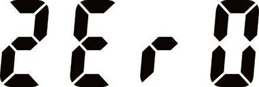
After a period of time using the device, there will be zero drift, in the absence of harmful gas environment, the display is not zero. To access this function, press the key to complete the clearing.
d. -rFS. Restore factory settings:

System parameter calibration error disorder or operation, causing the gas detection alarm is not working, enter the function.
Press and by changing the value of the input bit and blinking digit flashes on the 2222, press the key, if the LCD display good instructions recovery is successful, if the LCD display Err0, explained password.
Note: Restoring the factory calibration value refers to the value of restoring the factory settings. After recovery parameters, need to re-calibrate.
7. Special Instructions
This feature, if used improperly affect the normal use of the device.
In real-time concentration detection state, while Press the
 key, the LCD will display 1100, release the button to change the value of the input bit and blink blink 1111 position on the
 and
and
 , key press, LCD idLE, instructions to enter the program menu.
Press the key or
 key to switch on each menu, press the
 key to enter the function.
a. 1-UE version information

The LCD will display the version information systems, 1405 (the date of the software)
Press  or
or  key to display V1.0 (hardware version).
Press the key to exit this function, LCD idLE, can be carried out under a menu setting.
b. 2-FU calibration

LCD default calibration gas concentration values, and the last one is flashing, by pressing the and
and to change the value of the input calibration gas concentration value flashes bit and blinking digit, and then press the
 key, the screen displays '-' from moving left to right, after the show good, complete display settings idLE.
Detailed description of Calibration key [Chapter VIII of the calibration gas detection alarm].
c. 3-Ad AD value

Display the AD value.
d. 4-2H Display starting point

Set the minimum concentration began to show, and less than this value, it shows 0.
To set the desired value by pressing the and
and  to change the blinking digit and the blinking digit value, and then press the
 key to display the complete set after idLE.
e. 5-rE Factory Recovery

When there is no reaction, can not properly detect gas concentrations appear ventilation settings, enter the function.
Then the LCD will display 0000, and the last one is flashing, by pressing the  and
and  to change the value of the flashing digit and the blinking digit to enter the password recovery parameters (2222), and then press the
 key to display the good and idLE after complete recovery parameters.
Note: Restoring the factory Calibration value refers to the value of restoring the factory settings. After recovery parameters, need to re-calibrate.
Calibration gas detection alarm connection diagram shown in Figure 3, Table 8 for calibration connection diagram shows.
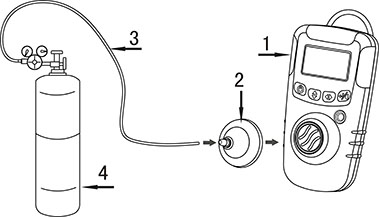
Figure 3 Connection diagram
| Table 8 Part Description | |
|
Item |
Description |
|
① |
Gas Detector |
|
② |
Calibration cap |
|
③ |
Hose |
|
④ |
Regulator and gas cylinder |
Pass into the calibration gas, stable value to be displayed, as shown in Table 9 were operating.
Table 9 Calibration Procedure
| Procedure | Screen |
Hold down the button and press the button and press the  button, release button, release |
1100 |
Enter the 1111 switch and flashing bit by and by and |
1111 |
Press the  button button |
idLE |
Double-click the button button |
2-FU |
Press the button, Will display the default calibration gas concentration value button, Will display the default calibration gas concentration value |
0500 (calibration gas concentration value) |
The actual value of the input switching concentration calibration gas flashing and blinking bit by bit on the key  and and  keys. keys. |
0600 (eg) |
Press the button, Screen '-' move from left to right. After displaying good, then display idLE. button, Screen '-' move from left to right. After displaying good, then display idLE. |
idLE |
Long press the button,return to the concentration detection interface , such as the calibration is successful, the concentration of the calibration value will be displayed, if the difference between the value of the standard gas concentration is large, the above operation again. button,return to the concentration detection interface , such as the calibration is successful, the concentration of the calibration value will be displayed, if the difference between the value of the standard gas concentration is large, the above operation again. |
600 (eg) |
To maintain the detector in good operating condition, perform the following basic maintenance as required:
• Calibrate, bump test, and inspect the detector at regular intervals.
• Maintain an operations log of all maintenance, calibrations, bump tests, and alarm events.
• Clean the exterior with a soft damp cloth. Do not use solvents, soaps, or polishes.
• Do not immerse the detector in liquids.
Table 10 Replacing the Battery
|
Item |
Description |
Detector parts diagram |
|
① |
Rear shell machine screws |
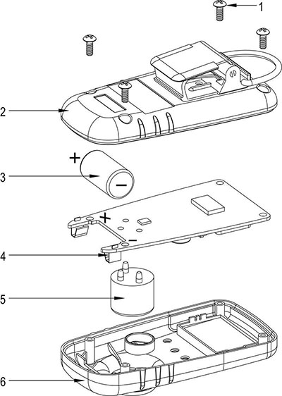 |
|
② |
Rear shell |
|
|
③ |
Battery |
|
|
④ |
PCB |
|
|
⑤ |
Sensor |
|
|
⑥ |
Front shell |
1. The measured value is not accurate
The gas detection alarm after a period of time used to detect concentrations may occur deviation, periodic calibration.
2. Concentration exceeds the set alarm value; there is no sound, light or vibration alarm.
Refer to Chapter 7 [Special instructions], the settings -AL5 inside to ON.
3. The battery inside the gas detection alarm can charge?
You can not charge, replace the battery power is exhausted after.
4. Gas detection alarm can not boot
a)Gas detection alarm crashes, open the detector housing, remove the battery, and then reinstall it.
b)The battery runs out, open the detector housing, remove the battery, and replace the same brand, same model battery.
5. What is the fault code information?
Err0 password error
Err1 set value is not within the allowed range Err2 calibration failure


