

Portable combustible gas leak detector Operating instructions


● Sensor Type: Catalytic sensor
● Detect gas: CH4/Natural gas/H2/ethyl alcohol
● Measure range: 0-100%lel or 0-10000ppm
● Alarm point: 25%lel or 2000ppm ,adjustable
● Accuracy: ≤5%F.S
● Alarm: Voice + vibration
● Language: Support English& Chinese menu switch
● Display: LCD digital display, Shell Material: ABS
● Working voltage: 3.7V
● Battery capacity: 2500mAh Lithium battery
● Charging voltage: DC5V
● Charging time: 3-5hours
● Ambient environment: -10~50℃,10~95%RH
● Product Size: 175*64mm( not including the probe)
● Weight: 235g
● Packing: Aluminum case
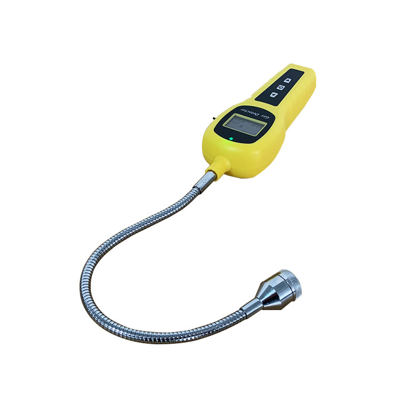
The dimension diagram is shown in Figure 1:
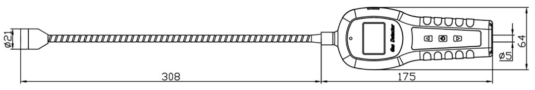
Figure 1 Dimension diagram
Product lists shown as table 1.
Table 1 Product list
|
Item No. |
Name |
|
1 |
Portable combustible gas leak detector |
|
2 |
Instruction manual |
|
3 |
Charger |
|
4 |
Qualification Card |
Detector Instruction
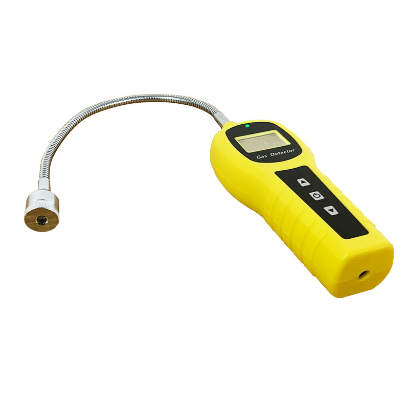
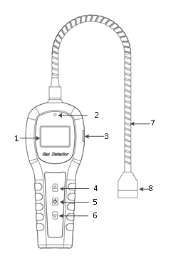
The specification of instrument parts is shown in Figure 2 and table 2.
Table 2 Specification of instrument parts
|
No. |
Name |
Figure 2 Specification of instrument parts |
|
1 |
Display Screen |
|
|
2 |
Indicator light |
|
|
3 |
USB charging port |
|
|
4 |
Up key |
|
|
5 |
Power button |
|
|
6 |
Down Key |
|
|
7 |
Hose |
|
|
8 |
Sensor |
3.2 Power on
Key description is shown in table 3
Table 3 Key Function
|
Button |
Function description |
Note |
|
▲ |
Up, value +, and screen indicating function | |
 |
Long press 3s to boot up Press to enter the menu Short press to confirm operation Long press 8s to restart the instrument |
|
|
▼ |
Scroll down, left and right switch flicker, screen indicating function |
● Long press 3s to start up
● Plug in the charger and the instrument will start automatically.
There are two different ranges of the instrument. The following is an example of a range of 0-100% LEL.
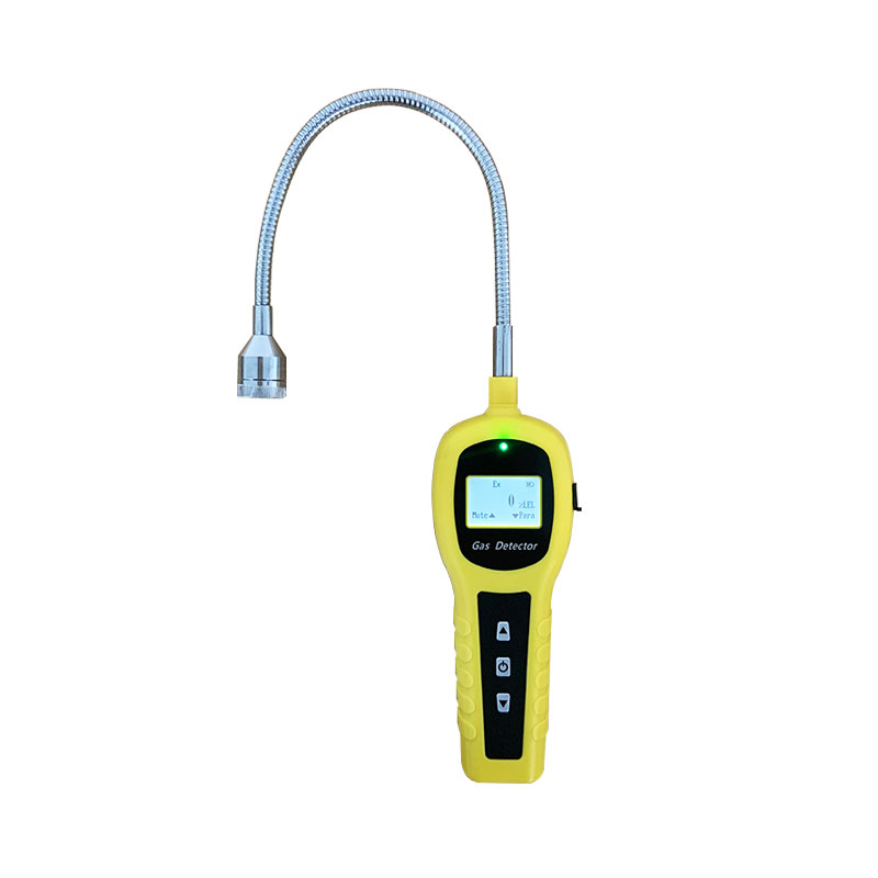
After starting up, the instrument displays the initialization interface, and after initialization, the main detection interface is displayed, as shown in figure 3.
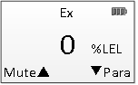
Figure 3 Main Interface
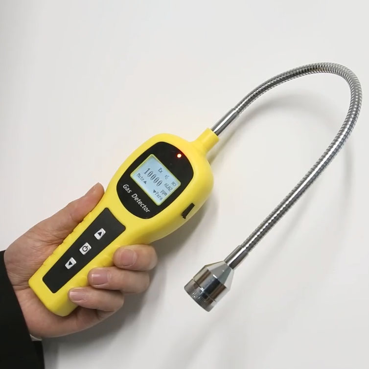
The instrument testing near the location of the need to detect, the instrument will show detected density, when the density exceeds bid, instrument will sound alarm, and accompanied by vibration, the screen above the alarm icon appears, as shown in figure 4, the lights changed from green to orange or red, orange for first alarm, red for the secondary alarm.
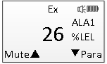
Figure 4 Main interfaces during alarm
Press ▲ key can eliminate alarm sound, alarm icon change to . When the instrument concentration is lower than the alarm value, the vibration and alarm sound stop and the indicator light turns green.
Press ▼ key to display instrument parameters, as shown in figure 5.
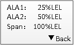
Figure 5 Instrument Parameters
Press ▼ key return to the main interface.
3.3 Main Menu
Press key on the main interface, and into menu interface, as shown in figure 6.
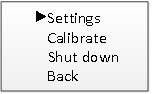
Figure 6 Main Menu
Setting: sets the alarm value of the instrument, Language.
Calibration: zero calibration and gas calibration of the instrument
Shutdown: equipment shutdown
Back: returns to the main screen
Press ▼or▲ to select function, press to perform an operation.
3.4 Settings
Settings Menu is shown in Figure 8.
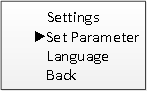
Figure 7 Settings Menu
Set Parameter: Alarm Settings
Language: Select system language
3.4.1Set Parameter
The settings parameter menu is shown in Figure 8. Press ▼ or ▲ to choose the alarm that you want to set, then press to execute operation.
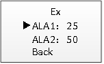
Figure 8 Alarm level selections
For example, set a level 1 alarm as shown in figure 9, ▼ change the flicker bit, ▲value add 1. The alarm value set must be ≤ the factory value.
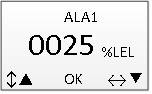
Figure 9 Alarm setting
After setting, press to enter the setting interface of alarm value determination, as shown in Figure 10.
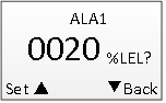
Figure 10 Determine the alarm value
Press, success will be displayed at the bottom of the screen, and failure will be displayed if the alarm value is not within the allowed range.
3.4.2 Language
Language menu is shown in Figure 11.
You can choose Chinese or English. Press ▼ or ▲ to choose language, press to confirm.

Figure 11 Language
3.5 Equipment calibration
When the instrument is used for a period of time, the zero drift appears and the measured value is inaccurate, the instrument needs to be calibrated. Calibration requires standard gas, if there is no standard gas, gas calibration cannot be performed.
To enter this menu, need to enter the password as shown in figure 12, which is 1111
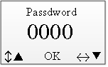
Figure 12 Password input interface
After completing the password input, press enter to the device calibration selection interface, as shown in Figure 13:
Select the action you want to take and press enter.

Figure 13 Correction type selections
Zero calibration
Enter the menu to perform zero calibration in clean air or with 99.99% pure nitrogen. The prompt for determination of zero calibration is shown in Figure 14 .Confirm according to ▲.
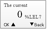
Figure 14 Confirm the reset prompt
Success will appear at the bottom of the screen. If the concentration is too high, the zero correction operation will fail.
Gas calibration
This operation is performed by connecting the standard gas connection flowmeter through a hose to the detected mouth of the instrument. Enter the gas calibration interface as shown in Figure 15, input the standard gas concentration.
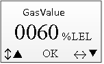
Figure 15 Set the standard gas concentration
The concentration of the input standard gas must be ≤ the range. Press to enter the calibration waiting interface as shown in Figure 16 and enter the standard gas.
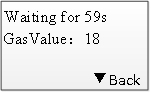
Figure 16 Calibration waiting interface
Automatic calibration will be executed after 1 minute, and the successful calibration display interface is shown in Figure 17.

Figure 17 Calibration success
If the current concentration is too different from the standard gas concentration, calibration failure will be shown, as shown in Figure 18.

Figure 18 Calibration failure
4.1Notes
1)When charging, please keep the instrument shutdown to save charging time. In addition, if switch on and charging, the sensor might be affected by the difference of charger (or the difference of charging environment), and in serious cases, the value might be inaccurate or even alarm.
2)It needs 3-5 hours for charging when the detector is auto-power off.
3)After get full charged, for combustible gas, it can work 12hours continuously (Except for alarm)
4)Avoid using the detector in a corrosive environment.
5)Avoid contacting with water.
6)Charge the battery every one to two-three months to protect its normal life if it is not used for a long time.
7)Please be sure to start the machine in normal environment. After starting, take it to the place where the gas is to be detected after the initialization completed.
4.2Common Problems and Solutions
Common Problems and Solutions as table 4.
Table 4 Common Problems and Solutions
|
Failure phenomenon |
Cause of the malfunction |
Treatment |
|
Unbootable |
low battery |
Please charge in time |
|
System halted |
Press the button for 8s and restart the device |
|
|
Circuit fault |
Please contact your dealer or manufacturer for repair | |
|
No response on the detection of gas |
Circuit fault |
Please contact your dealer or manufacturer for repair |
|
Display inaccuracy |
Sensors expired |
Please contact your dealer or manufacturer for repair to change the sensor |
|
Longtime no calibration |
Please calibrate timely | |
|
Calibration failure |
Excessive sensor drift |
Calibrate or replace the sensor in time |
Related products
-
Composite portable gas detector Instructions
System Description System configuration 1. Table1 Material List of Composite portable gas detector Portable pump composite gas detector USB Charger Certification Instruction Please check materials immediately after unpacking. The Standard is necessary accessories. The Optional is can be choose according to your needs. If you have no need to calibration, set the alarm parameters, or rea...
-
Compound Portable Gas Detector Operating Instru...
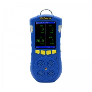
Product description The composite portable gas detector adopts 2.8-inch TFT color screen display, which can detect up to 4 kinds of gases at the same time. It supports the detection of temperature and humidity. The operation interface is beautiful and elegant; it supports display in both Chinese and English. When the concentration exceeds the limit, the instrument will send out sound, light and vibrat...
-
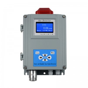
Single-point Wall-mounted Gas Alarm Instruction...
Technical parameter ● Sensor: infrared sensor ● Responding time: ≤40s (conventional type) ● Work pattern: continuous operation, high and low alarm point(could be set) ● Analog interface: 4-20mA signal output [option] ● Digital interface: RS485-bus interface [option] ● Display mode: Graphic LCD ● Alarming mode: Audible alarm -- above 90dB; Light alarm -- High intensity strobes ● Output control: relay o...
-
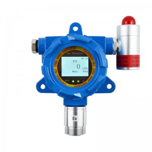
Fixed single gas transmitter LCD display (4-20m...
System Description System configuration Table 1 bill of materials for standard configuration of fixed single gas transmitter Standard configuration Serial number Name Remarks 1 Gas transmitter 2 Instruction manual 3 Certificate 4 Remote control Please check whether the accessories and materials are complete after unpacking. Standard configuration is a ne...
-

Composite portable gas detector Instructions
System Description System configuration 1. Table1 Material List of Composite portable gas detector Composite portable Gas Detector USB Charger Certification Instruction Please check materials immediately after unpacking. The Standard is necessary accessories. The Optional is can be choose according to your needs. If you have no need to calibration, set the alarm parameters, or read the...
-
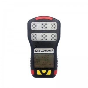
Portable compound gas detector User’s manual
System instruction System configuration No. Name Marks 1 portable compound gas detector 2 Charger 3 Qualification 4 User manual Please check whether the accessories are complete immediately after received the product. Standard configuration is a must-have for purchasing equipment. Optional configuration is separately configured according to your needs, if y...


